Microchip MCP6002-E/SN Dual Op-Amp: Features, Applications, and Circuit Design Guide
The Microchip MCP6002-E/SN is a dual operational amplifier (op-amp) that stands out for its combination of low power consumption, rail-to-rail input and output operation, and affordability. Housed in a compact 8-pin narrow SOIC package, it is an ideal choice for a vast array of analog circuit designs, particularly in battery-powered and portable applications where efficiency and space are critical.
Key Features of the MCP6002-E/SN
The popularity of the MCP6002 is built upon a robust set of features tailored for modern electronic design:
Low Power Consumption: With a typical quiescent current of just 100 µA per amplifier, the device significantly extends battery life in portable equipment.
Rail-to-Rail Input/Output (RRIO): This feature allows the input and output voltages to swing very close to the power supply rails (VSS and VDD). This maximizes the dynamic range in low-voltage applications, which is crucial when operating from a single supply voltage as low as 1.8V up to 5.5V.
Gain Bandwidth Product: The MCP6002 offers a 1 MHz gain bandwidth product, making it suitable for a wide range of audio, sensor interface, and signal conditioning tasks that do not require ultra-high speeds.
High DC Gain and Phase Margin: These characteristics ensure stable operation across a variety of feedback configurations, simplifying circuit design.
ESD Protection: With ESD protection rated up to 4 kV, the chip is more robust against electrostatic discharge events during handling and operation.
Extended Temperature Range: The ‘E’ suffix denotes an operating temperature range of -40°C to +125°C, making it suitable for industrial and automotive environments.
Primary Applications
The MCP6002's feature set makes it exceptionally versatile. Common applications include:
Sensor Signal Conditioning: Its RRIO capability is perfect for interfacing with transducers (e.g., temperature, pressure, light sensors) whose output signals are often near the supply rails.
Active Filters: It is commonly used to implement Sallen-Key or multiple-feedback (MFB) low-pass, high-pass, and band-pass filters for anti-aliasing or signal shaping.
Portable and Battery-Powered Devices: Its low power consumption is ideal for medical instrumentation, handheld meters, and remote sensors.
Voltage Followers/Buffers: The high input impedance and low output impedance make it an excellent choice for isolating stages within a circuit.
Analog-to-Digital Converter (ADC) Drivers: It effectively buffers and scales analog signals before they are digitized by a microcontroller's ADC.
Circuit Design Guide
Designing with the MCP6002 is straightforward, but adhering to best practices ensures optimal performance.
1. Basic Inverting Amplifier:
This circuit provides signal amplification with a 180-degree phase shift. The gain is set by the resistor ratio: Av = -Rf / Rin.
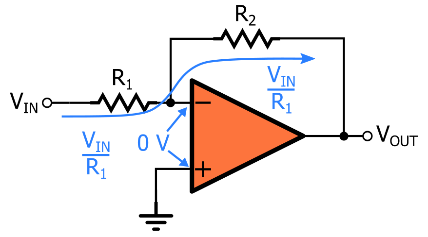
Component Selection: Choose resistor values (typically between 1kΩ and 100kΩ) that are low enough to avoid excessive noise but high enough not to overload the source and to keep power consumption minimal.
2. Basic Non-Inverting Amplifier:
This configuration amplifies the signal without inverting it. The gain is given by Av = 1 + (Rf / Rg).

Stability: The MCP6002 is unity-gain stable, meaning it can be used in this configuration with a gain of 1 (voltage follower) without oscillating.
3. Low-Pass Active Filter (Sallen-Key Topology):
This is one of the most common uses for a dual op-amp like the MCP6002, where each amplifier can be used for a separate filter stage.

Design Tip: Use online filter design calculators or simulation tools to determine the values of R and C based on your desired cut-off frequency.
4. Critical Layout and Bypassing:
Bypass Capacitors: Always use a 0.1 µF ceramic decoupling capacitor between the VDD pin and the VSS (ground) pin, placed as close as possible to the op-amp's supply pins. This is non-negotiable for stable operation, as it shunts high-frequency noise on the power line to ground.
PCB Layout: Keep input traces short to minimize noise pickup and stray capacitance. Separate high-frequency digital traces from sensitive analog inputs.
ICGOODFIND: The Microchip MCP6002-E/SN is a highly efficient and versatile dual op-amp that excels in low-voltage, power-sensitive applications. Its rail-to-rail capability and robust performance across a wide temperature range make it a reliable and cost-effective solution for designers tackling sensor interfaces, active filters, and portable device circuitry. Proper implementation, including careful supply bypassing and circuit configuration, unlocks its full potential.
Keywords: Low-Power Op-Amp, Rail-to-Rail Input/Output, Signal Conditioning, Active Filter Design, Battery-Powered Applications.

